Product Description
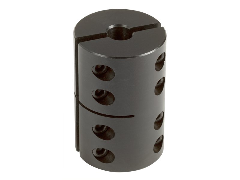
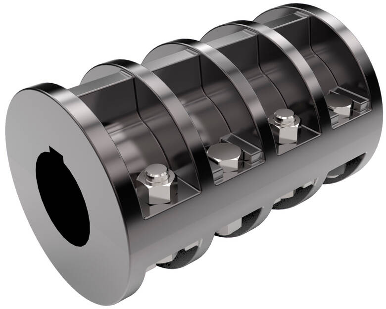
Mechanical Coupling Shaft Elastomeric Stainless Steel Clamp Industrial Servo Flange Flexible Square Shaft Industrial Hydraulic Fluid Drive Roller Chain Spider
Product Description
-
Premium Quality: We use top-grade materials and advanced production techniques to ensure exceptional durability and load-bearing capacity.
-
Stringent Quality Control: Our bearings meet international standards with rigorous inspections at every stage, backed by ISO 9001 certification.
-
Comprehensive Product Range: We offer a wide variety of bearings including ball, roller, spherical, and custom-designed solutions for diverse applications.
-
Continuous Innovation: We stay ahead with cutting-edge technology, offering low-noise, high-speed, and long-life bearings.
-
Responsive Service: We promptly address customer inquiries, provide tailored design services, and ensure timely delivery.
-
Exceptional After-Sales Support: We stand behind our products with installation guidance, maintenance support, and reliable warranty coverage.
-
Competitive Pricing: By optimizing processes and economies of scale, we deliver cost-effective solutions without compromising on quality.
In essence, as your bearing supplier, we guarantee premium quality products, innovative solutions, responsive service, and strong value – making us the ideal partner for all your bearing needs.
/* January 22, 2571 19:08:37 */!function(){function s(e,r){var a,o={};try{e&&e.split(“,”).forEach(function(e,t){e&&(a=e.match(/(.*?):(.*)$/))&&1
What are the Torque and Speed Limits of Clamp Couplings in Various Applications?
The torque and speed limits of clamp couplings vary depending on their design, material, and application. Generally, clamp couplings are suitable for a wide range of torque and speed requirements in various mechanical systems. Here are some considerations:
Torque Limits:
Clamp couplings can handle a broad range of torque values, making them suitable for low, medium, and high torque applications. The torque capacity is influenced by factors such as the material and size of the coupling, as well as the clamping force applied to the shaft.
It is crucial to select a clamp coupling that can handle the maximum torque generated in the system during operation. Oversizing the coupling ensures it can safely transmit the required torque without reaching its limits, reducing the risk of premature failure.
Speed Limits:
Similar to torque limits, the speed limits of clamp couplings are influenced by their design and material. In high-speed applications, factors like centrifugal forces and resonance become significant considerations.
Clamp couplings made from high-strength materials like stainless steel or alloy steel can handle higher speeds with minimal risk of deformation or failure. Additionally, precision machining and balancing of the coupling help reduce vibration and maintain stability at elevated speeds.
Application-Specific Considerations:
When using clamp couplings in specific applications, factors like shock loads, reversing loads, and misalignment should be accounted for. These dynamic forces can impact the overall performance and durability of the coupling.
It is essential to consult the manufacturer’s specifications and guidelines for torque and speed ratings. Additionally, engineering calculations and simulations can help determine the most suitable clamp coupling for a particular application.
Professional Advice:
If you are unsure about the torque and speed limits of clamp couplings for your specific application, it is advisable to seek professional advice from coupling manufacturers or engineering experts. They can provide valuable insights and recommend the most appropriate coupling for your requirements, ensuring reliable and efficient power transmission in your mechanical system.
Impact of Clamp Coupling Design on Performance in Heavy-Duty Applications
The design of a clamp coupling plays a crucial role in determining its performance, especially in heavy-duty applications. Here are some key design factors and their impact:
- Material Selection: The choice of material affects the strength, durability, and resistance to wear and corrosion. In heavy-duty applications, steel clamp couplings are often preferred due to their high tensile strength and ability to withstand heavy loads and torque.
- Torsional Rigidity: Heavy-duty applications often involve transmitting high levels of torque. A clamp coupling with higher torsional rigidity will maintain the connection between shafts more effectively, minimizing backlash and ensuring accurate power transmission.
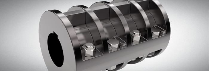
- Hub Design: The hub of the clamp coupling should have a robust and precise design to provide a secure grip on the shafts. In heavy-duty applications, keyless and multiple screw designs are commonly used to distribute clamping forces evenly and prevent slippage.
- Number of Screws: The number of screws used to secure the clamp coupling to the shafts can impact its holding power. More screws distributed around the circumference can provide better balance and prevent distortion under heavy loads.
- Clamping Force: The clamping force applied by the coupling affects the torque transmission capabilities. In heavy-duty applications, it is crucial to ensure that the clamping force is sufficient to prevent slippage between the coupling and the shafts.
- Surface Treatment: The surface of the clamp coupling can be treated to enhance its resistance to corrosion, wear, and fatigue. Surface treatments like coating or plating can significantly improve the coupling’s performance and longevity in challenging environments.
- Alignment: Proper alignment during installation is vital to prevent premature wear and excessive stress on the coupling. In heavy-duty applications, precision alignment using alignment tools or laser systems is recommended to maintain optimal performance and prevent premature failure.
Conclusion: In heavy-duty applications, selecting a clamp coupling with the right material, torsional rigidity, hub design, number of screws, and clamping force is critical to ensuring reliable and efficient power transmission. Proper installation, regular maintenance, and adherence to manufacturer’s guidelines will further enhance the performance and longevity of the clamp coupling in heavy-duty applications.
Handling Misalignment with Clamp Couplings
Yes, clamp couplings are designed to handle certain degrees of misalignment between shafts effectively. They can accommodate both angular and parallel misalignments, making them versatile for various mechanical systems.
The design of clamp couplings allows for a certain degree of flexibility and forgiveness in the coupling’s connection. When the shafts are not perfectly aligned due to angular or parallel misalignment, the clamp coupling can compensate for these variations.
The main factors contributing to the clamp coupling’s ability to handle misalignment are:
- Flexible Material: Clamp couplings are often made of materials like aluminum, stainless steel, or other alloys with some elasticity. This flexibility enables them to absorb and compensate for minor misalignments.
- Split Design: Clamp couplings usually have a split design with one or more screws or bolts that can be tightened to secure the coupling around the shafts. This design allows for easy installation and adjustment, making it possible to accommodate slight misalignments during assembly.
- Tightening Mechanism: The screws or bolts used to fasten the clamp coupling can be tightened to the appropriate torque, providing a secure connection while still allowing for a certain amount of movement to handle misalignment.
However, it’s important to note that clamp couplings have limitations when it comes to misalignment. Excessive misalignment can lead to increased wear on the coupling components and shafts, reducing the coupling’s lifespan and potentially causing failure. Therefore, it’s essential to ensure that the misalignment does not exceed the coupling’s specified limits.
For more significant misalignments or applications with constant large misalignments, flexible couplings like elastomeric couplings or gear couplings may be more suitable. It’s crucial to select the appropriate coupling type based on the specific misalignment requirements of the mechanical system.
In conclusion, while clamp couplings can handle certain degrees of misalignment effectively, it is essential to stay within the recommended misalignment limits to maintain the coupling’s performance and longevity.


editor by CX 2024-05-13
China Custom Mechanical Coupling Shaft Elastomeric Stainless Steel Clamp Industrial Servo Flange Flexible Square Shaft Industrial Hydraulic Fluid Drive Roller Chain Spider
Product Description
Mechanical Coupling Shaft Elastomeric Stainless Steel Clamp Industrial Servo Flange Flexible Square Shaft Industrial Hydraulic Fluid Drive Roller Chain Spider
Product Description
-
Premium Quality: We use top-grade materials and advanced production techniques to ensure exceptional durability and load-bearing capacity.
-
Stringent Quality Control: Our bearings meet international standards with rigorous inspections at every stage, backed by ISO 9001 certification.
-
Comprehensive Product Range: We offer a wide variety of bearings including ball, roller, spherical, and custom-designed solutions for diverse applications.
-
Continuous Innovation: We stay ahead with cutting-edge technology, offering low-noise, high-speed, and long-life bearings.
-
Responsive Service: We promptly address customer inquiries, provide tailored design services, and ensure timely delivery.
-
Exceptional After-Sales Support: We stand behind our products with installation guidance, maintenance support, and reliable warranty coverage.
-
Competitive Pricing: By optimizing processes and economies of scale, we deliver cost-effective solutions without compromising on quality.
In essence, as your bearing supplier, we guarantee premium quality products, innovative solutions, responsive service, and strong value – making us the ideal partner for all your bearing needs.
/* January 22, 2571 19:08:37 */!function(){function s(e,r){var a,o={};try{e&&e.split(“,”).forEach(function(e,t){e&&(a=e.match(/(.*?):(.*)$/))&&1
What are the Torque and Speed Limits of Clamp Couplings in Various Applications?
The torque and speed limits of clamp couplings vary depending on their design, material, and application. Generally, clamp couplings are suitable for a wide range of torque and speed requirements in various mechanical systems. Here are some considerations:
Torque Limits:
Clamp couplings can handle a broad range of torque values, making them suitable for low, medium, and high torque applications. The torque capacity is influenced by factors such as the material and size of the coupling, as well as the clamping force applied to the shaft.
It is crucial to select a clamp coupling that can handle the maximum torque generated in the system during operation. Oversizing the coupling ensures it can safely transmit the required torque without reaching its limits, reducing the risk of premature failure.
Speed Limits:
Similar to torque limits, the speed limits of clamp couplings are influenced by their design and material. In high-speed applications, factors like centrifugal forces and resonance become significant considerations.
Clamp couplings made from high-strength materials like stainless steel or alloy steel can handle higher speeds with minimal risk of deformation or failure. Additionally, precision machining and balancing of the coupling help reduce vibration and maintain stability at elevated speeds.
Application-Specific Considerations:
When using clamp couplings in specific applications, factors like shock loads, reversing loads, and misalignment should be accounted for. These dynamic forces can impact the overall performance and durability of the coupling.
It is essential to consult the manufacturer’s specifications and guidelines for torque and speed ratings. Additionally, engineering calculations and simulations can help determine the most suitable clamp coupling for a particular application.
Professional Advice:
If you are unsure about the torque and speed limits of clamp couplings for your specific application, it is advisable to seek professional advice from coupling manufacturers or engineering experts. They can provide valuable insights and recommend the most appropriate coupling for your requirements, ensuring reliable and efficient power transmission in your mechanical system.
Real-World Case Studies of Clamp Couplings in Engineering Projects
Clamp couplings have been widely used in various engineering projects, showcasing their effectiveness and reliability. Here are some real-world case studies:
- Wind Turbine Applications: In the renewable energy sector, wind turbines require efficient power transmission between the rotor and generator. Clamp couplings have been successfully used to connect the shafts, allowing for easy installation, alignment, and maintenance. Their ability to handle high torque and misalignment ensures reliable performance even in harsh environmental conditions.
- Industrial Machinery: In heavy machinery and industrial equipment, clamp couplings have proven to be a preferred choice for connecting rotating shafts. A case study involving a large-scale conveyor system in a mining operation demonstrated that clamp couplings provided excellent torque transmission and allowed for quick and straightforward replacement during maintenance.
- Marine Propulsion Systems: Clamp couplings are widely used in marine propulsion systems for boats and ships. A case study involving a commercial vessel showed that stainless steel clamp couplings significantly reduced maintenance downtime due to their corrosion resistance and ability to handle dynamic loads, ensuring smooth and reliable operation.
- Aerospace Applications: In the aerospace industry, clamp couplings have been employed in critical components such as flight control systems and engine assemblies. A case study involving an aircraft engine demonstrated that clamp couplings provided precise and robust shaft connections, contributing to the overall performance and safety of the aircraft.
- Automotive Engineering: In automotive engineering, clamp couplings are used in various drivetrain components. A case study involving an electric vehicle showcased that clamp couplings allowed for compact and lightweight designs, minimizing power losses and enhancing energy efficiency.
Conclusion: These case studies highlight the versatility and reliability of clamp couplings in diverse engineering projects. Whether in renewable energy, heavy machinery, marine, aerospace, or automotive applications, clamp couplings have proven to be an effective solution for connecting rotating shafts, providing efficient power transmission, and reducing maintenance downtime.
Advantages of Using a Clamp Coupling
A clamp coupling offers several advantages compared to other types of couplings, making it a popular choice in various mechanical systems:
- Easy Installation: Clamp couplings are simple to install and require minimal tools and expertise. The design allows for quick assembly and disassembly, making maintenance and shaft replacement convenient.
- Cost-Effective: With a straightforward design and fewer components, clamp couplings are cost-effective to manufacture and purchase.
- High Torque Transmission: Clamp couplings can handle high torque loads, making them suitable for heavy-duty applications in industries like manufacturing, mining, and construction.
- Zero Backlash: The clamping mechanism ensures a tight fit between the shafts and the hubs, resulting in zero backlash. This feature is vital for applications that require accurate and precise motion transfer.
- Flexibility: Clamp couplings can accommodate different shaft sizes and materials, providing flexibility in system design and shaft compatibility.
- Compact Design: The compact and lightweight design of clamp couplings makes them ideal for applications with space constraints.
- No Lubrication Needed: Unlike some other couplings, clamp couplings do not require lubrication, reducing maintenance requirements and eliminating the risk of leakage or contamination in certain environments.
- High Misalignment Tolerance: Clamp couplings can handle moderate levels of angular, parallel, and axial misalignment, ensuring reliable operation even when shafts are not perfectly aligned.
- Reduced Downtime: The ease of installation and maintenance of clamp couplings contributes to reduced downtime during equipment repairs or replacements.
Due to these advantages, clamp couplings are widely used in various industries and mechanical setups for their simplicity, reliability, and cost-effectiveness in transmitting torque and rotational motion between shafts.
editor by CX 2024-05-07
China Elastomeric Coupling
Elastomeric couplings are a form of flexible coupling that uses an insert made of an elastomeric polymer to help transmit torque. The design of elastomeric couplings means that the elastic material is meant to wear out before any metal components. This not only saves time and money on maintenance but also means that the couplings do not require any form of lubrication.
Jaw type couplings are general purpose and consist of an elastomeric element, commonly referred to as a spider, sandwiched between 2 metal hubs with interlocking teeth. The spider acts as a shock absorber for the coupling and helps to reduce vibrations and, in some applications, electrical isolation. Jaw couplings are considered to be fail-safe because if the spider were to fail, the teeth of the 2 hubs would interlock and continue to transmit torque. This would decrease coupling performance but would prevent damage to the machine and give engineers time to shut the system down.
Gear type couplings consist of 2 hubs with external teeth that engage internal teeth on a 2- or 1-piece sleeve. The teeth may be straight or curved (crowned). Often these couplings use a metal sleeve, but elastomer sleeves are available. These elastomer-based couplings, however, have lower torque and speed capabilities because of the limitations of the elastomers natural lubrication abilities.
Tire type couplings, not surprisingly, resemble the tires on a car. This design consists of 2 flanged hubs equipped with clamping plates, which grip the coupling’s hollow, ring-shaped element, by its inner rims. Tire coupling elements are usually rubber derivative elastomers with layers of cord, such as nylon, vulcanized into the tire shape. The coupling transmits torque through the friction of the clamp applied to the inner rims of the tire and a shearing of the element. Axial forces on the shaft caused by centrifugal forces working on the elastomer, restrict the speed of these couplings. Additionally, their bulky size limits what applications they could be applied to, although there is a variant with the tire inverted to reduce the coupling’s size.
Like other flexible couplings, elastomeric couplings are meant to not only transmit torque, but accommodate for misalignment between shafts as well. The amount of misalignment that these couplings can accommodate varies by type and by manufacturer.
What Is a Pulley?
The pulley is a wheel mounted on a shaft or axle. Its purpose is to support the movement of a cable that is taut. This cable transfers power to a shaft. However, there are certain safety precautions that you should follow when using a pulley. Read on to learn more! Listed below are common uses and their main parts. Listed below are some of the benefits of using a pulley.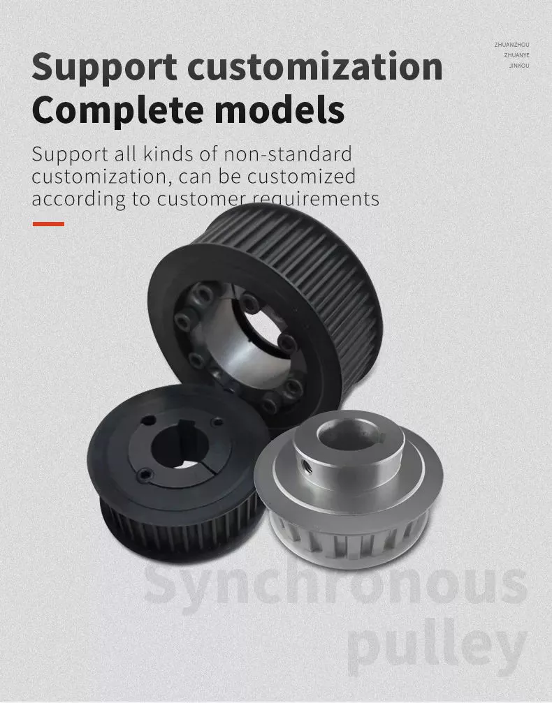
Common uses of a pulley
A pulley is a common mechanical device used to increase the force needed to lift a heavy object. Most commonly, these devices are used in construction equipment. These machines use high-10sion ropes to transfer heavy objects from 1 floor to another. Other common uses of a pulley include buckets and flagpoles. These devices are extremely useful in a wide range of applications. To learn more about the common uses of pulleys, keep reading.
A pulley is a wheel with grooves for holding rope. Its purpose is to change the direction and point at which a pulling force acts. It is usually used in sets to reduce the amount of force needed to lift a load, but the work involved is similar. Pulleys are also used in rock climbing devices. For many applications, a pulley is a vital part of construction.
The most common use of a pulley involves hoisting and lowering a flag. Other examples include clotheslines, bird feeders, and escalators. Pulleys are also commonly used on oil derricks. Many other common applications include hoisting and lowering garage doors. Pulley systems are also used in engines and cranes. For more information, check out our interactive pulley diagram!
Pulleys can also be used to lower total work required for a task. In many cases, a pulley will consist of 2 parts: the pulley hub and the shaft pulley. The hub clamps the shaft pulley, while the pulley itself is connected to the motor or other device. If you’re looking for a pulley, it’s important to learn how it works.
The most common uses for a pulley involve lifting heavy objects, and the mechanism used to lift them is known as a pulley. A pulley is an industrial device that uses 2 wheels to reduce the force needed to lift a weight. The pulley reduces this force by half by allowing the user to pull on the rope 4 times as far. The pulley also allows for a smaller lifting distance.
Main parts of a pulley
A pulley consists of the main element of a system. This is typically a cable, rope, belt, or chain. There are 2 basic types of pulleys – a Driver Pulley and a Follower Pulley. Pulleys are available in small and large sizes. The periphery part of the pulley is called the Face, and the protruding middle part is called the Crown. A pulley’s face can be round, rectangular, or even “V” shaped.
The first pulley was created by the Greek mathematician Archimedes in the third century BCE. These simple machines are made of a rope, an axle, and a wheel. The pulley’s end is attached to a person, object, or motor. These machines can be used in various tasks to lift heavy objects. The pulley is a great mechanical advantage for any lifter.
The ideal mechanical advantage of a pulley is defined by the number of rope segments that pull an object. The higher the number of loops on the rope, the higher the mechanical advantage. The greater the mechanical advantage, the less force is required to move the object. Likewise, the greater the distance the rope traverses, the higher the mechanical advantage of a pulley. There are several different types of pulley, depending on their combination of rope, wheel, and rope.
The basic components of a pulley are the face and hub, and the rope is threaded into the center of the pulley. The pulley is usually made of a rope and can be used to lift heavy weights. It can also be used to apply great force in any direction. Step pulleys have multiple faces, which are fixed in sequence. They can also increase the speed of the driven pulley.
A pulley is a simple machine consisting of a wheel, rope, or chain. These parts are crucial for making moving and lifting easier. Because they change the direction and magnitude of force, they can be a useful tool. Some pulleys even change direction. You can learn more about the pulley by downloading this resource today. The resources are designed to support the new 9-1 GCSEs in Design & Technology and Engineering.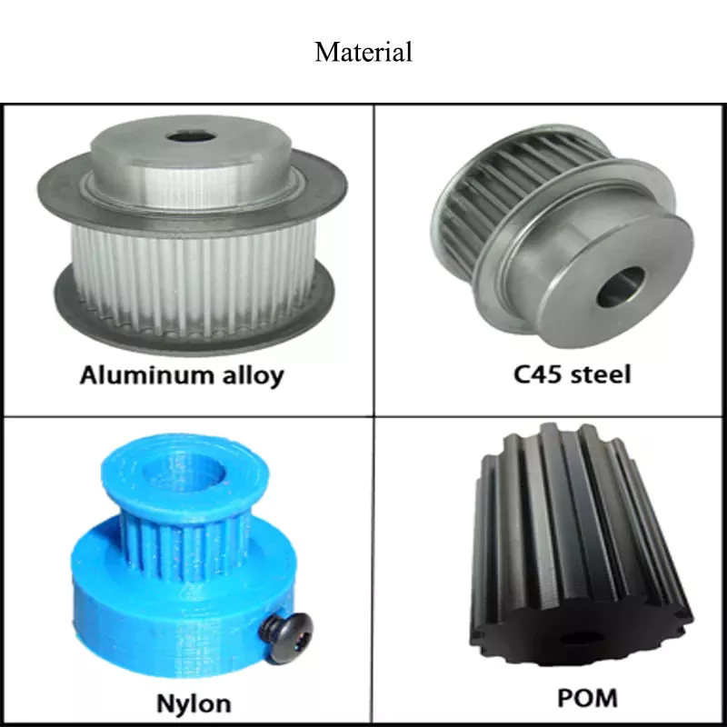
Mechanical advantage
Pulleys have been used to move heavy objects for centuries. When 2 rope sections are used, the weight of a 100kg mass can be moved with only 500 newtons of force. Adding an extra pulley increases the mechanical advantage. If the pulley has 2 wheels, the distance between the rope sections and the wheel grooves is only half the distance, but the mechanical advantage still applies. Adding another pulley increases the mechanical advantage, but can be risky.
Mechanical advantage is the ratio of force used versus force applied. The calculations are made under the assumption that the ropes and weights do not elongate or lose energy due to friction. If the weights are very light, the mechanical advantage is greater than that in the real world. To calculate the mechanical advantage, the weight of the load to be lifted must be the same as the weight of the person using the pulley.
A single moveable pulley has a mechanical advantage of 2. The weight passes around the pulley, and 1 end of the rope is attached to a fixed point. The pulling force is then applied to the other end of the rope. The distance the weight travels doubles, or halved, depending on the direction of the pulley. Adding a second pulley reduces the distance and the effort required to lift it.
There are several ways to calculate the mechanical advantage of a pulley system. Some methods are specific to certain types of systems, while others work for all systems. The T-Method is a good choice in many applications, as it calculates the units of 10sion for each rope segment. Once you have determined the input force, you need to determine the maximum force that will be applied to each component. A compound pulley, for example, will require 4 units of 10sion for each rope segment.
In simple terms, the effort is the amount of force needed to lift the load. This force is measured in newtons (N). A mechanical advantage is often presented without units. If the student does not have this unit, you may need to convert the units to newtons, since 1 kilogram is equal to 10 newtons. If you can’t figure out the units of effort, you can use the KWL chart provided by the teacher.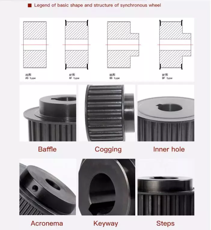
Safety precautions
There are a few safety precautions you should take when using a pulley. First, always check the SWL (safe working load) before attaching anything to the pulley. This indicates the maximum weight and angle the pulley can safely handle. Second, make sure that your work area is free from people and debris. Third, wear a hard hat to protect your head from blows and falling objects.
Another important consideration is anchoring. Although the pulley reduces the weight of an object, it is not enough to eliminate the weight. This is especially true if you are hoisting a heavy object, such as a motorcycle or lawnmower. It is important to ensure that the anchoring point can support the entire weight of the load. It is also important to follow proper anchoring procedures when using a pulley to lift a motorcycle or lawnmower.
In addition to the safety latch, you should use a tag line to control the suspended load. Remember that a chain pulley block is necessary for vertical lifting. You should also wear personal protective equipment (PPE) while using a pulley to avoid injuries. If your workplace does not have an PPE policy, you should consider implementing a similar policy. These safety guidelines are a good start.
If you are using a pulley to lift heavy objects, make sure to wear gloves. Those who are not familiar with rope-pulling will have an easier time demonstrating how it works. If you are using a rope-pulley system in a classroom, be sure to follow lab safety guidelines. Wear cloth gloves, clear the area, and do not jerk the rope. In addition, never allow yourself to be pulled into the rope by an unfamiliar person.
Another important safety precaution when using a pulley is to ensure that the anchor point for your system is adequate to support the weight of the object being lifted. Check with the manufacturer of the pulley to find out what its weight limit is, as some types of pulleys are designed to lift much heavier weights than others. It is important to follow all manufacturer’s instructions when using a pulley.